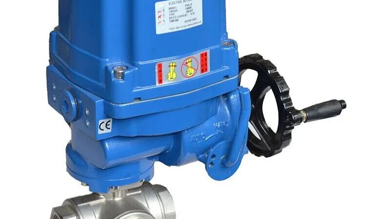
Installation Guide: Electric Ball Control Valve
Introduction
We are a leading control valve manufacturer in China, providing high-quality valves and control actuators designed to meet the unique demands of various industries.
Electric ball control valves play a critical role in fluid control systems across industrial, commercial, and residential settings. Proper installation is key to ensuring optimal performance, safety, and longevity. This comprehensive guide outlines each step of the installation process—from pre-installation checks to wiring and final testing.
Whether you’re a technician, engineer, or DIY enthusiast, this guide will help you avoid common mistakes and achieve reliable valve operation.
Pre-Installation Guidelines
Before installation, follow these essential steps to ensure a safe and efficient setup:
1. Review Safety Instructions
-
Read the manufacturer’s safety manual thoroughly.
-
Understand handling procedures, electrical hazards, and operational precautions.
-
Ensure all personnel are briefed on safety protocols.
2. Verify Valve Specifications
-
Check actuator labels for pressure ratings, temperature ranges, and media compatibility.
-
Cross-reference with the manufacturer’s documentation for clarification if needed.
3. Select an Appropriate Installation Location
-
Install in a dry, protected area to prevent moisture or environmental damage.
-
Ensure adequate space for maintenance and future access.
-
Avoid high-vibration or high-stress zones.
4. Depressurize and Cool the System
-
Shut off the fluid source and release residual pressure.
-
Allow hot systems to cool to prevent burns or valve damage.
5. Inspect and Clean Piping
-
Remove dirt, corrosion, or debris using flushing, brushing, or compressed air.
-
Ensure a clean, unobstructed flow path.
6. Install an Upstream Filter (If Required)
-
Use filters for fluids with particulates to protect valve internals.
-
Schedule regular filter cleaning or replacement.
7. Gather Tools and Fittings
Tools:
-
Adjustable wrench set
-
Pipe thread sealant
-
Welding tools (if applicable)
-
Wire strippers, screwdrivers
Fittings:
-
Threaded, flanged, or welded adapters as per system requirements
Wiring the Actuator
Correct wiring is essential for actuator performance and system safety. Follow these steps precisely:
1. Identify the Wiring Diagram
-
Locate the wiring diagram on the actuator or in the manual.
-
Ensure it matches the actuator’s model and voltage specifications.
Typical Terminal Labels (e.g., JP Fluid Control):
-
L (Live): AC Power (120V/240V)
-
N (Neutral): AC Return
-
G (Ground): Earth Ground
-
COM: Control Signal Common
-
NO: Open Signal
-
NC: Close Signal
2. Prepare the Wires
-
Strip 6–8mm of insulation from wire ends.
-
Use ferrules or crimp connectors for secure, reliable connections.
3. Connect Power Wires
-
AC Actuators:
-
Connect L to the hot wire.
-
Connect N to the return line.
-
Connect G to ground.
-
-
DC Actuators:
-
Connect Positive (+) and Negative (–) wires accordingly.
-
4. Attach Control Signal Wires
-
Manual Operation: Connect NO and COM to a switch.
-
Automated Systems (PLC/DCS):
-
Connect signal input (e.g., 4–20mA, 0–10V) to control terminals.
-
Confirm correct polarity and signal compatibility.
-
5. Secure All Connections
-
Tighten all terminals to prevent loosening from vibration.
-
Use cable glands to strain-relieve cables and protect connections.
6. Test the Actuator
-
Power on the system and send a control signal.
-
Observe valve response:
-
Clockwise = Closing
-
Counter-clockwise = Opening
-
-
If unresponsive, check power, wiring, or obstructions.
7. Final Inspection
-
Verify no exposed wires or damaged insulation.
-
Confirm actuator housing is sealed (IP65/IP67 rated).
-
Check for abnormal heat buildup during operation.
Installation Best Practices
1. Proper Alignment
-
Ensure pipes are aligned before tightening to avoid stress.
-
Use flexible couplings if movement is expected.
2. Avoid Over-Tightening
-
Follow specified torque ratings to prevent damage to connections.
-
Use a cross-pattern tightening method for flanged joints.
3. Periodic Maintenance
-
Lubricate moving parts as needed.
-
Inspect electrical terminals annually.
-
Monitor valve response time to detect early signs of wear.
Troubleshooting Common Issues
| Issue | Possible Cause | Solution |
|---|---|---|
| Valve not moving | No power | Check circuit breaker, verify wiring |
| Partial operation | Low voltage | Ensure input matches actuator rating |
| Leakage | Loose or damaged fittings | Re-tighten or replace seals |
| Erratic movement | Contaminated valve seat | Clean or replace valve components |
Conclusion
A successful electric ball control valve installation depends on careful preparation, accurate wiring, and thorough testing. By following this guide, you ensure safe, efficient, and durable valve operation.
Always refer to the manufacturer’s manual for specific instructions or consult a qualified technician for advanced installations. Proper setup today helps prevent costly issues down the line.Know more about Google SEO Directory


Leave a Reply